Products
Sound Transmission Loss
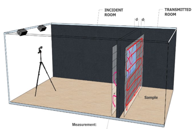
Conventional measurement procedures for the characterization of sound Transmission Loss (TL) imply practical difficulties and high costs, especially in terms of testing environments. With the use of the PU sensors from Microflown Technologies, an in-situ characterization can be achieved in a matter of minutes by directly measuring the incident and transmitted acoustic fields. The sound Transmission Loss can be represented using 2D sound visualization tools or traditional spectral representations. The TL calculation sub-module is available for both Scan&Paint 2D and Analyser software.
ANALYSER + TL
- One or multiple sensors
- Scanning and fix point
- No camera required
- No spatial representations, only spectral quantification
- Characterize one or multiple partitions
- Very fast methodology
- Measurement campaign and task lists can be predefined
SCAN & PAINT 2D + TL
- One sensor
- Scanning based method
- It requires a camera
- Spatial representations and spectral results
- Characterize multiple partitions through scans
- Additional setup time and post-processing required
- Sound leakage and TL results from the same data
This sound transmission loss measurement procedure is based on regular Scan & Paint tests. All you need to do is to drive a sound source with broadband noise and carry out a scan with a Microflown PU probe over the target areas. Two scans need to be performed: one over the emitter side and the other at the receiver side. The transmission loss software module will merge the two scans, calculate the local sound transmission loss and illustrate via colormaps, potentially revealing acoustic leakage, mounting errors or installation defects.

